Introduction and application of Borehole TV imaging technology
The core-drilling method is a conventional detecting method and has been widely used in the detection of cast-in-place concrete piles. This method can analyze the defects of the pile body, especially loose and broken pile, intercalated mud and other conditions. It can be used to determine the exact thickness of the pile bottom slag, judge or identify more complex rock soil properties.
However, the core-drilling method has great subjectivity and limitations in the detection process. After the core-drilling method is applied, the Borehole TV is used to take a video of the drilled hole, which can help to check the pile quality and the bearing layer, and further determine the pile quality and the conditions of the bearing layer, making a clearer judgment on the integrity of the pile body. It is also an effective means to resolve disputes over the authenticity of the core sample between the organizations responsible for the project quality.
In the process of engineering quality inspection of tubular piles, put the Borehole TV tester into the pile hole to observe various abnormalities and defects in the pile, check the joints, and quantitatively analyze the pile quality, broken area, fracture and crack location, length, width, direction and others, which can control the engineering quality of piles better.
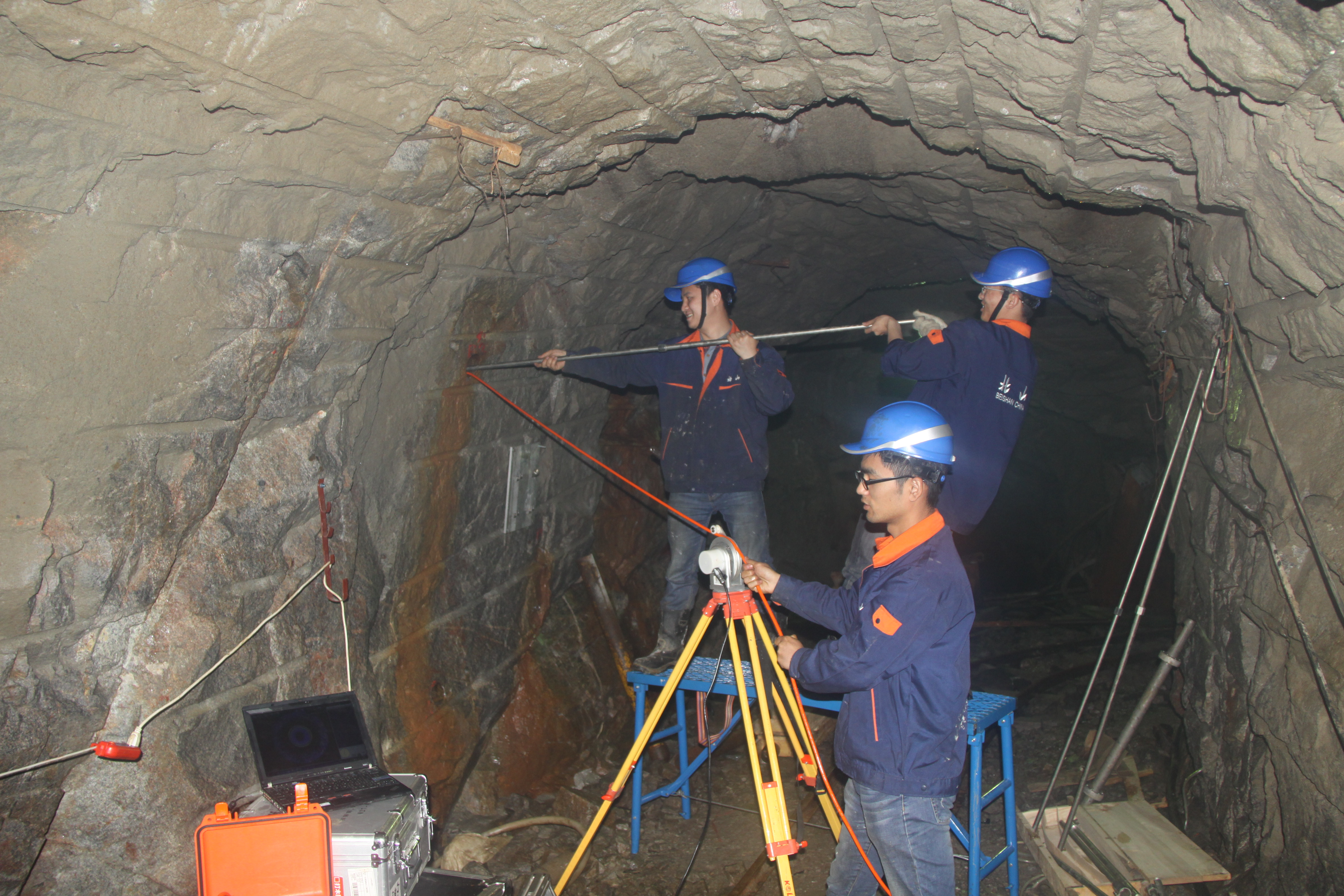
The Borehole TV tester is mainly composed of the ground part and the part in the hole. The ground part includes a controller, a tripod, a winch, a pulley and a depth counter; the part in the hole includes a camera probe and a cable. The camera probe is composed of a panoramic camera, LED light, and glass cover.
The wall of the drill hole is illuminated by the LED light, the panoramic camera captures the image of the hole wall, and the image information is transmitted to the controller and the display terminal via the cable. The entire collection process is completed by the image collection control software system, which arranges and merges the collected images and records them on the computer.
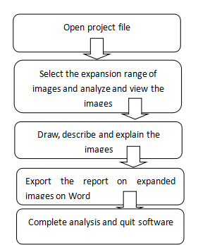
The electronic compass installed in the probe is used to calibrate the orientation of the image. Generally, the due north of the test site is set to 0° after the magnetic declination is corrected, and the angle increases in the clockwise direction. The image is positioned and selected by the electronic compass. The imaging of the hole wall is expressed in the form of a flat expansion view through the image processing software, and the image in the hole can be recorded.
Data acquisition
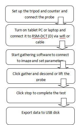
The borehole TV imager can truthfully and clearly reflect the image of borehole walls. To reflect clear and timely image of boreholes, the instrument records and expands the images within effective imaging range of the probe in real time while the probe moves up and down, and save the imaging in video format.
The probe lighting intensity may be adjusted by gathering software to confirm the adjustment of effective imaging range of probe. It is also equipped with auto-speed reminder to guarantee the definition of image gathered in boreholes without omission.
As for data storage, the program has taken into full consideration the engineering particularity. During real-time gathering, the software is able to automatically save the images gathered from a certain depth as pictures which may be directly viewed on site after the test gathering is finished.
As for human-computer interaction, the instrument may be controlled by a tablet PC or laptop, which is convenient and fast. The program is flexible and simple and truly meets the purpose of friendly human-computer interactive interface design.


