1.Application and technology introduction of pile driving analyzer
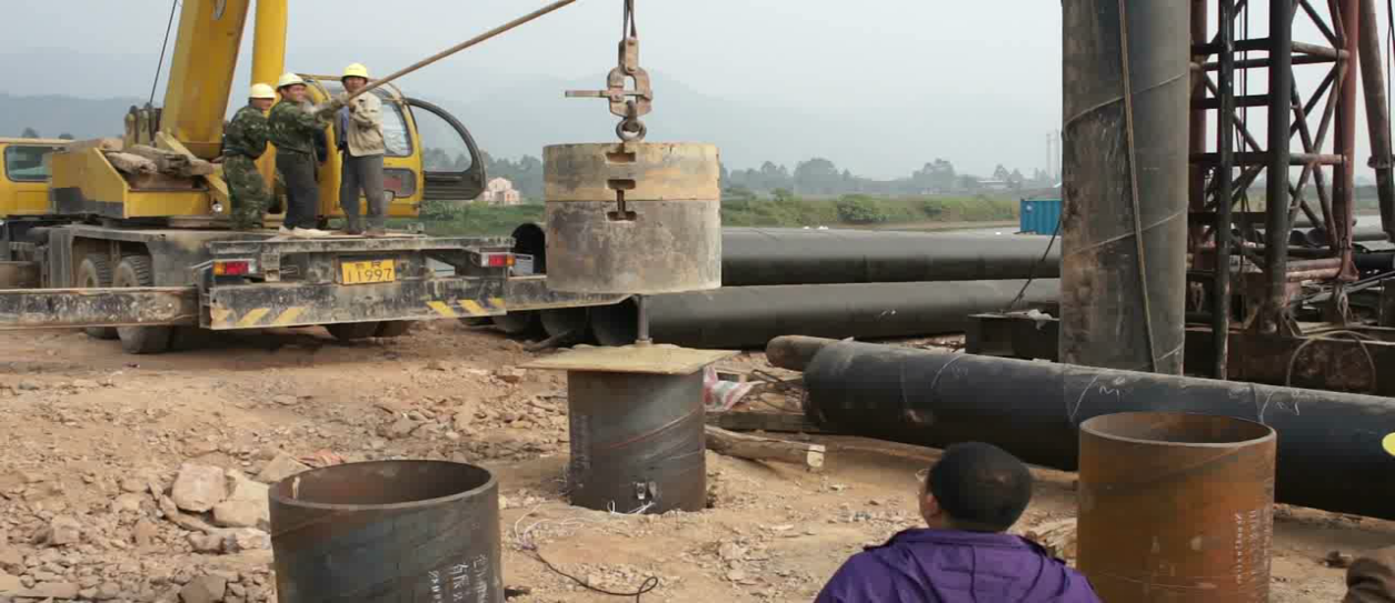
The high-strain pile testing method is a dynamic testing method by impacting the top of pile with a hammer, and in the process of downward transmission of shock pulse along the pile body, and making the pile-soil generate enough relative displacement, so as to stimulate the resistance of the soil around the pile and the pile-end bearing capacity.
1) Judge whether the vertical bearing capacity of a single pile meets the design requirements.
2) Detect the defect and position of pile body and judge the integrity category of pile body.
3) Analyze the resistance on the pile side and the pile end.
4) Drive the pile and monitor it.
Principle of high-strain dynamic load testing
Test Schematic Diagram
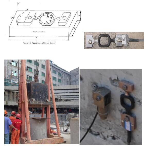
A hammer hit the pile tip, and make the relative displacement of the pile - soil produce enough to fully stimulate resistance and pile end bearing capacity of pile soil, by installing pile under pile cap on either side of the force and acceleration sensor of pile stress wave signal, analysis and processing of application of the theory of stress wave force and velocity time history curve, so as to determine the bearing capacity of pile and evaluate the integrity of pile.
Usually the high-strain testing system shall include the vibration excitation system, measurement system and measured object, etc.
Vibration excitation system: It is used to excite the test object or the equipment system which has the test object to generate vibration (namely, the system which generates the vibration excitation signal), e.g. hammer in high-strain test.
Measurement system: The whole system which converts the measured vibration quantity into electrical signals, and converts, amplifies, displays, records, stores, calculates and analyzes them. What we measure is electrical signals, and they can be recovered to the measured physical parameters through the calibration coefficient of the sensor.
Measured object: It is the test object, e.g. pile and soil in the high-strain test.
 Force sensor
Strain ring F=EAε=ρAC2ε
 Install the acceleration sensor on the hammer to measure the force: F=ma
Speed sensor
Accelerator ZV=ρAC∫a dt
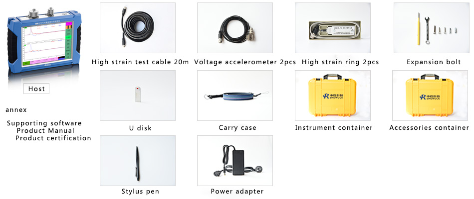
2.Equipment components and advantages
 Features
1. Original instantaneous floating point amplification technology can take into account the distortionless acquisition of strong and weak signals;
2. Removable lithium battery is provided, desktop charger is supported and spare battery can be provided to ensure that the field work will not be interrupted;
3. The bilingual operation in both Chinese and English is supported;
4. The balance of strain bridge can be adjusted automatically to reduce the impacts of initial deformation of strain ring on signal acquisition and eliminate the signal zero drift;
5. The three-dimensional correction function for shallow defect is owned and the defect can be located accurately;
6. Built-in Bluetooth and WIFI can realize the function of real-time monitoring of wireless uploading;
7. With fast signal acquisition pace, the 60 hammers/min signal acquisition can be completed and the piling monitoring testing can be carried out in real time;
8. 8.4-inch true-color LCD screen is used, the curve is clear and direct and the backlight can be adjusted;
9. Portable high-strength engineering plastic shell with small volume and light weight can make operation easy;
10. 24-bit A/D combination design has large dynamic range and high signal to noise ratio;
11. Self-test for sensor installation status can be conducted in the field in real time;
12. Touch screen operation, friendly software interface and easy operation;
13. Analysis results by Case method, F-ZV curves and upper and lower traveling wave curves are displayed in the field;
14. With adjustable screen brightness, it can be used in a variety of lighting conditions;
15. Background color and curve color can be adjusted to meet customer needs.
3. Precautions
Treatment of pile head: The broken layer on the top of concrete pile and the soft or incompact concrete shall be chiseled away.
Side grinding and drilling and screw selection: The top surface of the pile head shall be flat and the central axis of pile head shall coincide with the central axis of upper part of pile body.
Installation of sensor: All main reinforcements of pile head shall go straight through the bottom of concrete protective layer on the top of pile, and be on the same height.
Parameter settings: The area with a distance equal to the pile diameter from the top of pile shall be wrapped with the steel plate with 3mm~5mm thickness; or set the hooped reinforcement within an area with a distance of 1.5 times of the pile diameter from the top of pile, with the spacing not greater than 100mm. One layer ~two layers of reinforcing meshes shall be set on the top of pile, with the spacing within 60mm~100mm.
Selection of hammer and hammer pad (sand and plywood): The concrete strength grade of pile head shall be 1~2 grades higher than the concrete grade of pile body, and shall not be lower than C30.
Guiding device: The sectional dimension at the test point of pile head in the high-strain testing method shall be the same as the sectional dimension of the original pile body.
Displacement monitoring: The pile top shall be leveled with a spirit level.
4. Data analysis
CASE method and CAPWAPC method are adopted to analyze the measurement results, and the fundamental principle is described below:
1. Introduction to the principle of CASE method:
Approximate assumption of CASE method
- The impedance of pile body is constant, that is, the sectional area of pile body is unchanged, the material of pile body is homogenous and there is no obvious defect.
- Only consider the dynamic damping at the bottom of pile, ignore the dynamic damping of pile-side soil, and the static damping always remains constant.
- The stress wave has no energy consumption and signal distortion in the transmission process.
- The friction resistance of each point on the pile side is unchanged within the time period of (t1~t1+4l/c).
Assumes that the impact velocity peak time t1, the pile bottom reflection corresponding time t2=t1+2L/C,According to the measured force and speed curve F(t)、V(t),Can be derived using the case method calculation formula for calculating the bearing capacity of pile:

For such as cross section pile, Integrity coefficient of following the first defect of pile head can be derived using next calculation formula:

Among:

Rx--- Resistance of pile soil above defect X; Defect location according to the corresponding time tx of defects reflection wave can be derived using next calculation formula:

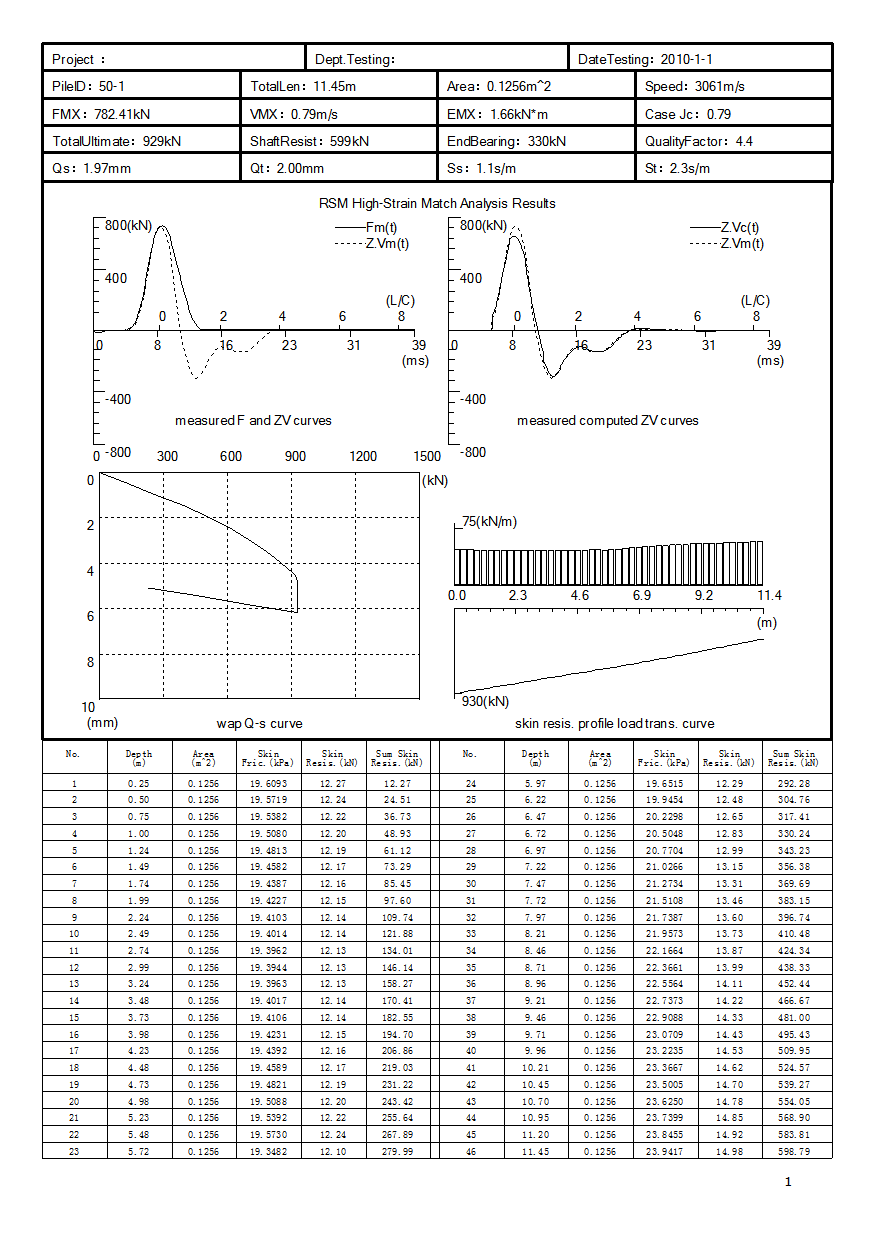
The measured curve fitting method adopted more complex pile - soil mechanics model, the measured force or speed or upgoing wave as a boundary condition to carry on the fitting, the fitting is complete calculation curve should be consistent with the measured curve, the friction pile lateral soil should be consistent with geological data, the calculated value of penetration should be consistent with the actually measured value, thus get the vertical bearing capacity of pile and pile integrity。
2. Introduction to the principle of CAPWAPC method
CAPWAPC (Case Pile Wave Analysis Program – Continuous version) is a curve fitting calculation program. It assumes the pile and soil model, and according to the force and speed time travel curve measured when the top of pile is under the action of impact force, takes the force (or speed) time travel curve as the input in the wave equation calculation, determine one group of soil model parameters as the calculation input, and after it is calculated by the program, obtain the speed (or force) time travel curve. Assuming that this group of soil parameters does not coincide with the practical situation of pile-side and pile-tip soil, the calculated force (or speed) time travel curve generally cannot coincide with the measured force (speed) time travel curve. To make the calculated force (or speed) time travel curve coincide with the measured force (speed) time travel curve, it is required to adjust the soil parameters to make them get close to the practical situation so as to make the calculated force (or speed) time travel curve match the measured force (speed) time travel curve, and the group of soil parameters obtained will be the final fitting result. This group of soil parameters includes the ultimate bearing capacity of pile, pile-side friction resistance distribution, pile-tip resistance, maximum elastic deformation value and damping value of pile-side soil and pile-tip soil. The fitting can also give the Q~s curve of simulated static load test, and if the resistance of pile-side and pile-end soil can be fully exerted, the above bearing capacity is the vertical ultimate bearing capacity of single pile.
5. On-site Troubleshooting
1) The difference in signal amplitude of the forces between both sides is too big.
Causes:
Eccentric hammer (shake of hammer when there is no guide frame; the guide frame is not placed horizontally; the pile cushion is not placed horizontally, etc.)
The sensitivity coefficient is set.
Control objective:
The difference shall be controlled within the specified range
Ensure that the sensitivity corresponds to the numbers.
2) The acceleration signal shocks in advance
Causes:
AC interference (alternating current is used on site and is not effectively grounded)
The interference of other vibration on site
Control objective:
Use dry cell as much as possible or ground the used alternating current effectively
Eliminate the vibration interference on site
3) The test signal shocks severely
Causes:
The sensor is installed loosely or not firmly (the drilling hole is too big or tilts), the pile cushion is inappropriate, the expansion bolt is poor, or the setting of filtering parameters is unreasonable.
Control objective:
Grind the sides flatly, select appropriate drill bit, ensure that the drilling distance is accurate, use good expansion bolt, make the sensor against the pile side closely, and set reasonable parameters.
4) When the product is in receiving state, it receives continuous random signals or there is no signal generated after hammering.
Causes:
The sensor is damaged, and the sensor is triggered in advance (the acceleration channel is more sensitive than the force channel, and when driving the pile around, weak vibration can stimulate the acceleration channel)
Control objective:
The sensor is normal, the connector is connected properly without short circuit, and there is no large interference.
5) The peak value of speed and force does not coincide
Causes:
The impedance in shallow part of the pile changes; the soil-side resistance in shallow part of the pile is huge; the non-linearity of concrete at the measuring point causes the force value to be extremely high; when the wave of hammering force rises slowly or the pile is very short, the soil resistance or the pile-bottom reflected wave has an impact; the pile cushion is too thick.
The selected wave velocity is inappropriate.
The sensitivity coefficient is incorrect.
The sensor is installed skew.
Control objective:
The peak value of speed and force shall be proportional at the beginning stage and does not need to coincide
6) The value of force or speed does not return to zero at last
Causes:
The concrete has plastic deformation or crack; the spacing of drilling holes does not match the sensor, and the sensor is installed by force; the collection time is short, and the vibration does not stop within the collection time period;
Control objective:
The collection length should be enough; drill holes in the uniform concrete.
7) The value of penetration is unclear
Causes:
The hampering penetration of pile is not monitored, and after the displacement curve is obtained purely through integration of acceleration for multiple times, the penetration is estimated according to the final displacement value.
Control objective: Monitor the pile deformation with a high-precision instrument.
Other auxiliary method can be adopted to verify it.
8) The difference of values among several times of hammering is big
Causes:
The thixotropic effect causes the bearing capacity to drop continuously; every time after hammering, the sensor is not reinforced in real time;
Control objective:
Make good preparation, collect the waveform at a single time, and hammering for several times is not allowed.
Summary:
The measured data problems mainly include:
Problem with sensor
Problem with cable
Problem with sensor installation
Serious defect with pile body
Problem with sensor calibration coefficient
Problem with setting
6. CAPWAPC Report Display


| Identification |
Meaning |
Hidden Function |
| P |
Project name: The construction site being tested |
Click it to enter the setting interface of sampling delay points |
| F |
File name: The file name used to save the current signal curve file. Note: the stored file name is in the format of “*.RPD3”. |
|
| L |
Preset pile length: The value of “pile length under test point” set by the user in “Setting” sub-menu. |
Click to enter the screen protection and backlight adjustment setting interface |
| C |
Preset wave velocity: The value of “wave velocity of test point” set by the user in “Setting” sub-menu. |
Click to change the color of curve |
| A |
Area: The value of “sectional area of test point” set by the user in “Setting” sub-menu. |
|
| T |
Sampling interval: The sampling interval of current curve or the sampling interval of next sampling. This value can be set only through manual selection. In “Save”, this parameter will be recorded in the file. |
Click to enter the sampling interval selection interface |
| Jc |
Soil damping coefficient: The value of “Case coefficient Jc” set by the user in “Setting” sub-menu. |
|
| D |
Density: The value of “density of test point” set by the user in “Setting” sub-menu. |
Click to enter the trigger level setting interface |
 |
Battery level of instrument: It can dynamically display the battery level of instrument. The more the green part in the battery icon is, the more the current remaining battery level is, and there is the percentage prompt. |
|
| 2013/02/19 |
System time: The current time of internal clock in the system. When “Saving” this time, it will be automatically recorded in the file. |
Click to exit and go to the main interface |
 |
Strain sensor balance indication. The first lamp indicates the status of E1, and the second lamp indicates the status of E2; if the lamp is red, it indicates exception; if the lamp is yellow, it means unbalanced, and if the lamp is green, it means balanced. |
|

| Identification |
Meaning |
| P |
Project name: The construction site currently tested. |
| F |
File name: The file of current signal curve. |
| L |
Pile length: The pile length below the test point which is calculated according to the set wave velocity when the wave velocity is constant; or the set pile length below the test point when the pile length is constant. |
| C |
Wave velocity: The wave velocity which is calculated according to the set pile length below the test point when the pile length is constant; or the set wave velocity when the wave velocity is constant. |
| +a1+a2 |
Acceleration channel: The acceleration channel currently taking part in the calculation; click it to enter the designated acceleration channel taking part in the calculation. |
| +e1+e2 |
Strain channel: The strain channel currently taking part in the calculation; click it to enter the designated acceleration channel taking part in the calculation. |
Adjust F/
Adjust ZV |
Click it and Adjust F/Adjust ZV will display alternately to select the curve F or ZV to be adjusted. |
| Zoom |
Click it to compress or unfold current curve. |
| Up |
Click it to zoom in the curve F or ZV, which corresponds to the curve selected in Adjust F/Adjust ZV. |
| Down |
Click it to zoom out the curve F or ZV, which corresponds to the curve selected in Adjust F/Adjust ZV. |
| Left |
Click it to move the curve F or ZV left, which corresponds to the curve selected in Adjust F/Adjust ZV. |
| Right |
Click it to move the curve F or ZV right, which corresponds to the curve selected in Adjust F/Adjust ZV. |
 |
Battery level of instrument: It can dynamically display the battery level of instrument. The more the blue part in the battery icon is, the more the current remaining battery level is, and there is the percentage prompt. |
| 2013/2/19 |
System time: The current time of internal clock in the system. |


