Overview
The high-strain pile dynamic load method is to impact the pile top with a heavy hammer, test the velocity and force time-history curves near the pile top, and determine the vertical compressive bearing capacity and the integrity of the pile body through wave theory analysis.
The high-strain PDA method actually includes three methods: hammer penetration test method, wave equation method and static-dynamic method. Hammer penetration is an empirical method, mainly suitable for small and medium friction piles, and has been basically replaced by the wave equation method; the wave equation method is actually the most widely used method in China; the static and dynamic method began in the late 1980s. , which is a reasonable improvement to the wave equation method in terms of reducing the wave propagation effect and improving the reliability of the bearing capacity test results.
The PDA method is a kind of impact pulse with high energy applied to the top of the pile, and the impact pulse produces a certain permanent displacement between the pile and the soil in the process of propagating down the pile body.
The so-called "high" strain gauge pile is relative to the "low" strain gauge pile. High-strain test piles use dozens or even hundreds of kilonewtons of heavy hammer to hit the top of the pile, so that the dynamic displacement of the pile is close to the settlement level of the conventional static load test pile, so that the resistance of the rock and soil at the pile side and pile end is large enough to fully use, that is, all or most of the soil around the pile produces plastic deformation, which is intuitively manifested as the penetration of the pile. However, for end-supported piles and super-long friction piles embedded in hard bedrock, it seems conceptually impossible to make the soil below the pile and at the top of the pile into a plastic state, regardless of the static load or high strain test.
The strain of high strain piles is usually in the range of 0.1‰~1.0‰. For ordinary steel piles, the pile body strain exceeding 1.0‰ is close to the corresponding deformation of steel; for concrete piles, depending on the strength of the concrete, the amount of strain corresponding to the obvious plastic deformation of the pile body is about 0.5‰~1.0‰. The strain of low-strain piles is generally less than 0.01‰.
Test purpose
(1) Determine whether the vertical bearing capacity of a single pile meets the design requirements.
(2) Detect the defects and positions of the pile body, and determine the integrity category of the pile body.
(3) Analysis of pile side and pile end resistance.
(4) Carry out piling monitoring.
Basic assumption of high strain
In principle, the high-strain dynamic test pile is simplified as a one-dimensional elastic linear wave dynamics problem:
1) Assume that the pile material is homogeneous and isotropic.
2) Assume that the pile is a linear elastic member.
3) Assume that the pile is a one-dimensional member.
4) Assume that the wavelength of the longitudinal wave is much larger than the cross-sectional dimension of the rod.
5) Assume that failure occurs only at the pile-soil interface.
Application
1) This method is suitable for testing the vertical compressive bearing capacity and integrity of the pile body;
2) Monitor the hammer energy transfer ratio when the prefabricated pile is driven in, and provide a basis for the selection of pile driving process parameters and pile length.
3) For large-diameter bottom expansion piles and large-diameter cast-in-situ piles with slow-varying Q-S curve characteristics, this method is not suitable for testing the vertical compressive bearing capacity.
4) When testing the vertical compressive bearing capacity of cast-in-situ piles, there should be on-site experience and reliable static and dynamic comparison verification data under similar conditions in the region.
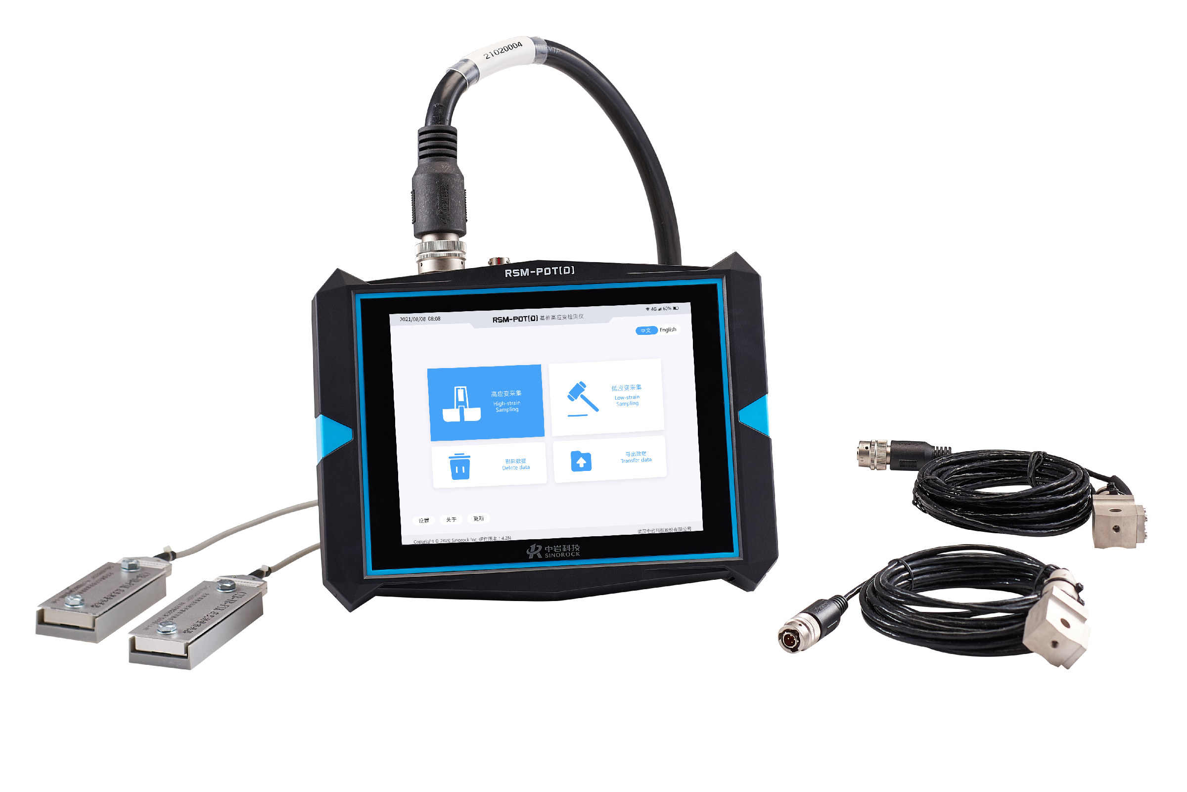
Equipment and requirements
The high-strain dynamic pile test system is mainly composed of three parts: sensors, pile dynamic testers, and impact equipment (weight hammer, guide frame, and decoupling).
Sensor requirements
A sensor is a component that converts the measured physical quantity into an electrical quantity that can be easily transmitted and processed. At present, in high strain testing piles, strain transducers are generally used to measure the force of the section near the top of the pile, and acceleration sensors (accelerometers) are used to measure the motion state of the section near the top of the pile.
1. force sensor - tool strain transducer
Usually, a tool-strain transducer is used to detect the force on the section of the pile body in a high-strain testing pile. Its appearance is shown in the figure. It has an elastic aluminum alloy ring frame, and four foil resistors are attached to the inner wall of the frame. , the resistance pieces are connected to form a bridge, when the axial force is applied, two pieces are under compression, and the other two pieces are under tension.
strain transducer
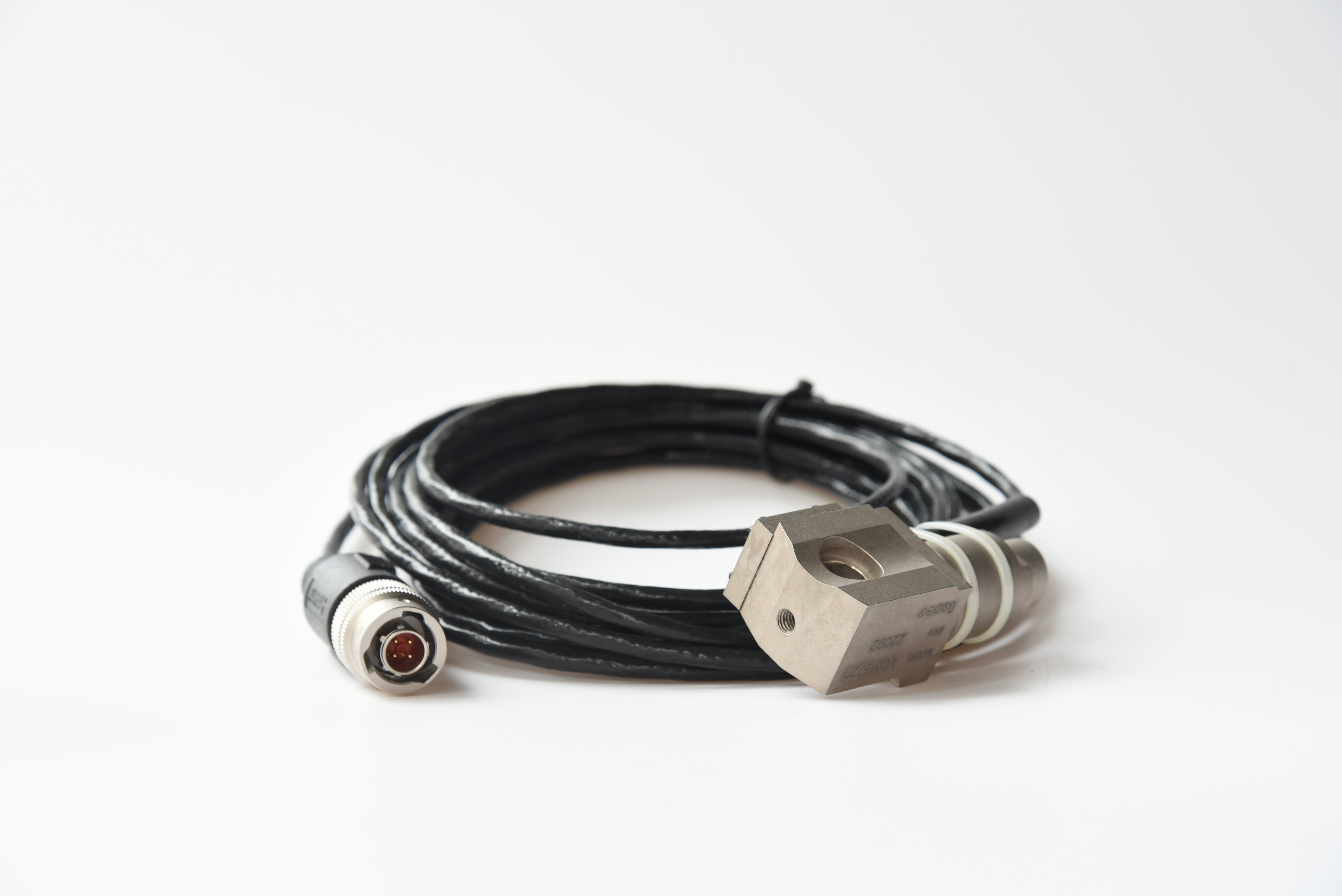 Accelerometer
In any other case, such as using a self-made free-fall hammer, the range of the accelerometer should not be less than 1000g. This also includes testing with an accelerometer mounted on the hammer body, and recommends the use of a heavy hammer and a low fall.
Impact equipment
Hammering equipment for on-site high-strain PDA testing falls into two categories: precast pile driving machines and free-fall hammers with guides.
The following factors should be considered when choosing hammer weight:
1) Measure the bearing capacity. The greater the bearing capacity, the heavier the hammer; the greater the proportion of the middle-end resistance in the bearing capacity, the heavier the hammer is required.
2) The influence of pile diameter. The larger the pile diameter, the greater the inertia of the pile itself, the lower the matching ability between the hammer and the pile, and the heavier the hammer is required. In addition, the increase of the pile diameter will also increase the elasticity of the soil, resulting in an increase in the hammer weight requirements.
3) The influence of pile length. The longer the pile, the greater the attenuation of the stress wave during the propagation process, and the harder it is to stimulate the resistance of the middle, lower and end of the pile, so the required hammer weight is heavier.
4) The influence of rock and soil elasticity. The elastic limit of the pile side and pile tip soil is relatively large. The greater the elasticity of the soil, the greater the relative displacement of the pile and soil required to stimulate the rock-soil resistance, and the heavier the hammer weight is required.
5) The impact of pile pads. The choice of pile pads should be based on the premise of fully stimulating the rock-soil resistance, and the softer pile pads should be selected as much as possible.
6) Advocate "strike with heavy hammer and strike low". Although "light hammer high fall" can increase the hammering energy, it often breaks the pile head. High-strain pile dynamic load test should vigorously promote "heavy hammer and low fall".
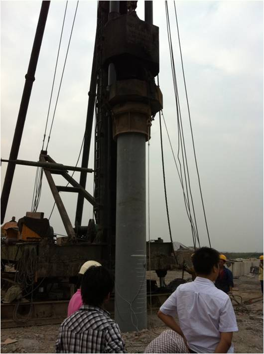
Guide Rod Hammer
Hammer equipment for high strain PDA testing should have a solid guide.
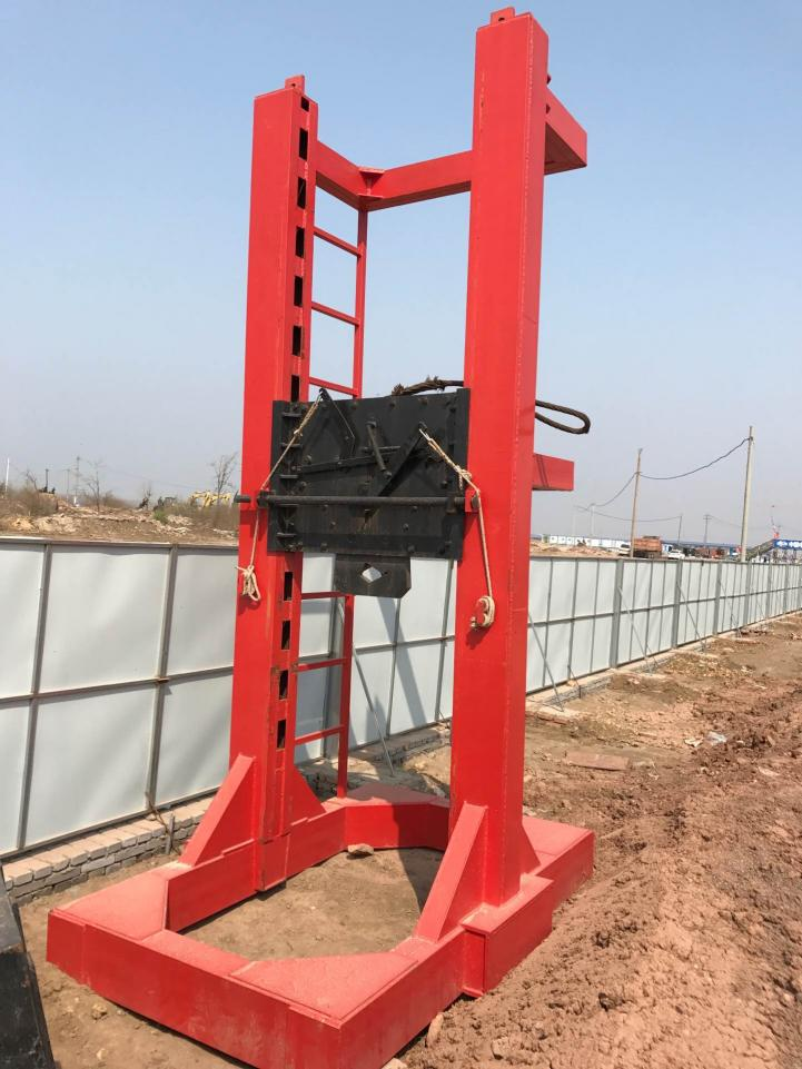 High Strain Guides Frame and Hook
On-site testing
1. Installation of hammering device
In order to reduce the eccentricity of the hammering and avoid crushing the pile head, the hammering device should be vertical, and the hammering should be stably centered. These measures are important to ensure the quality of the test signal. For the self-made free-fall hammer device, the chassis of the guide frame and the foundation soil under it should have enough contact area to ensure that the guide frame will not tilt after bearing the load.
2. Sensor installation
In order to reduce the stress concentration generated by hammering on the top of the pile and compensate for the eccentricity of the hammering, the sensor should be installed symmetrically at a suitable position at a specified distance from the top of the pile. During testing, at least two measuring sensors for impact force and impact response (particle motion speed) should be installed symmetrically, as shown in the figure for sensor installation.
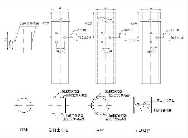 Schematic diagram of sensor installation (unit: mm)
3. Pile pad or hammer pad
For the self-made free-fall hammer device, pile pads should be set on the top of the pile head, and the pile pads can be made of 10-30mm thick wood or plywood, and a thin layer of sand should be laid on the pile pads.
4. Heavy hammer low fall
When free-fall hammers are used, heavy hammers with low fall should be used, and the maximum hammering distance should not be greater than 2.5m. According to the wave theory analysis, the maximum hammering stress on the pile top is only related to the initial velocity of the hammer hitting the pile top, and the initial velocity of the hammer hitting the pile top is proportional to the square root of the falling distance. The higher the drop distance, the greater the hammering stress and eccentricity, and the easier it is to break the pile head.The high impact of the light hammer cannot effectively increase the energy transmitted by the heavy hammer to the pile and increase the displacement of the pile top, because the duration of the force pulse is not only related to the hammer pad, but also mainly related to the hammer weight; the narrower the hammer pulse, the less time the wave propagates Inhomogeneity, that is, the more obvious the inhomogeneity (inertia effect) of the force and movement of the pile body, the more the influence of the dynamic resistance of the soil in the measured waveform will be intensified, while the static soil resistance related to the displacement will show a trend of segmental play, making the bearing Force test analysis error increases.In fact, if the hammer weight is increased to more than 5% to 10% of the estimated ultimate bearing capacity of a single pile, a long-lasting force pulse action similar to that of the Statnamic method can be obtained. At this time, because the wave propagation effect in the pile body is greatly weakened, the rock-soil resistance at the pile side and pile end is closer to the load transfer characteristics of the pile under static load. Therefore, "heavy hammer and low fall" is the basic principle to ensure the accuracy of the high-strain method to detect the bearing capacity, which is conceptually different from the low-strain method that makes full use of the wave propagation effect (narrow pulse) to accurately detect the defect location.
Project Case
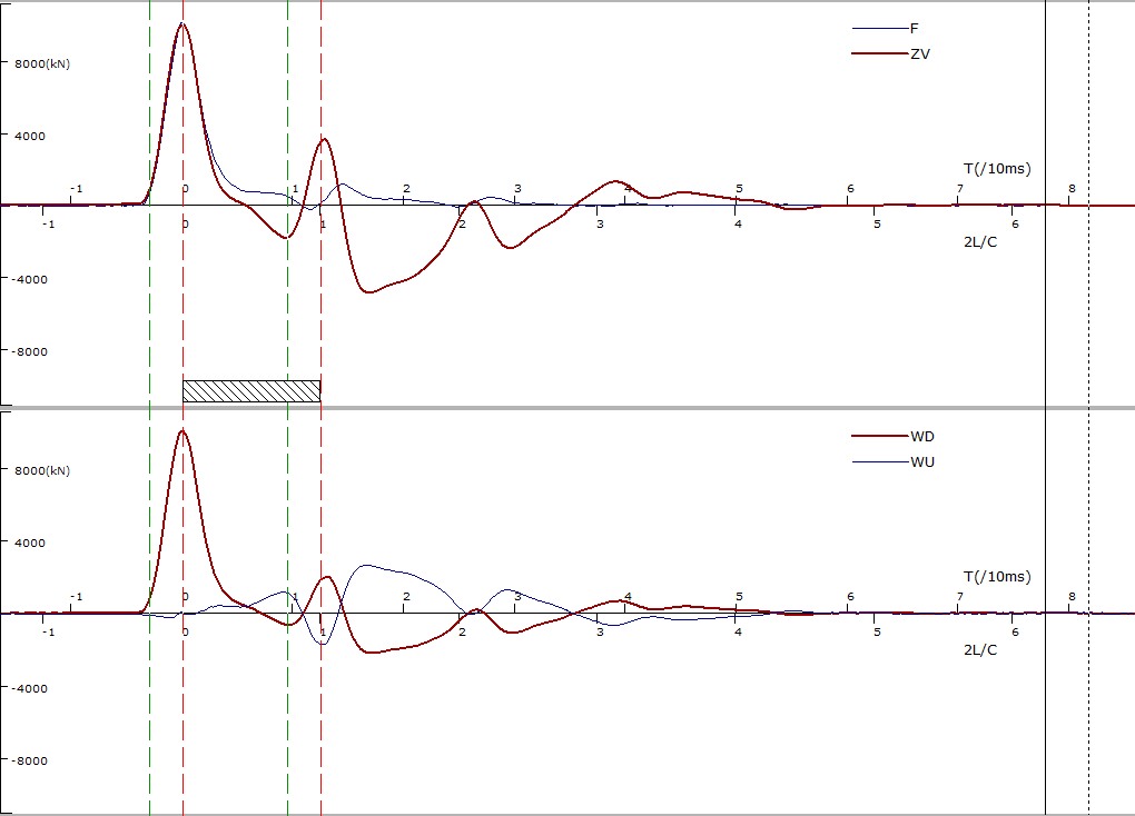
Bored cast-in-situ pile, pile diameter 0.8m, pile length 27m below the measuring point, pile tip bearing layer is silty clay, design value is 1800kN.
The test uses a 60kN weight hammer with a drop distance of 1m. The measured waveform is shown in the figure. The penetration is 7mm, and the vertical compressive bearing capacity of the single pile calculated by Case method is 3728kN. Meet the design requirements.